Designing stainless steel structures
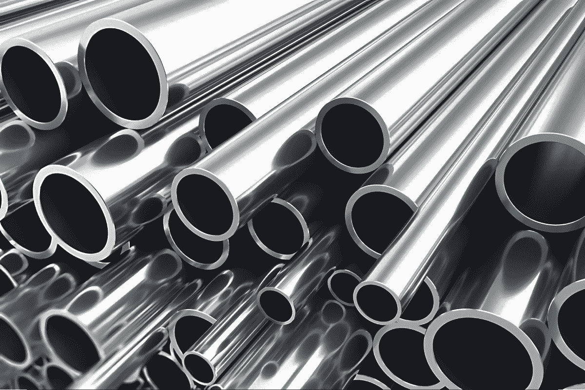
Stainless steel is increasingly used in construction, not only as cladding or architectural details, but also as a fully-fledged load-bearing material. Its advantage is high corrosion resistance combined with good strength and plasticity, which translates into lower maintenance requirements, a longer period without repairs, and a stable appearance of elements over time. In outdoor structures, infrastructure facilities, buildings with high humidity, or exposed architecture, this is as important an argument as load-bearing capacity itself.
The basis of “stainlessness” is the spontaneous formation of a thin, impermeable layer of chromium-rich oxides on the steel’s surface. This layer is stable, non-porous, and impermeable. When scratched, it rebuilds itself in the presence of oxygen, which is why in many environments, steel does not require classic protective coatings. However, it should be remembered that the stability of the passive layer depends on the composition of the steel, the surface finish, and the aggressiveness of the environment. In design practice, this means that the selection of material and detail should take into account not only “whether the steel will rust,” but also whether it will maintain the expected appearance and whether local corrosion will occur in areas subject to particularly harsh environmental conditions.
This article is based on the book “Podręcznik projektowania konstrukcji ze stali nierdzewnych, wydanie czwarte” published by the Rzeszów University of Technology, which is an accurate translation of the “Design Manual for Structural Stainless Steel, 4th Edition, SCI 2017.” The following content is only a general overview of the topic. For those interested in the subject, we highly recommend delving into the literature.

Selection of grade and identification of corrosive environment
In the design of stainless steel structures, the decision on the selection of the grade is as important as the selection of the cross-section. Different stainless steels offer different combinations of strength, weldability, and resistance to corrosive environments, so the goal is not to choose the “best” steel, but the steel that is appropriate for the exposure. The right choice avoids both premature corrosion problems and unnecessary cost overruns resulting from the use of a grade that is too high-alloyed.
Three families dominate in construction practice: austenitic, ferritic, and duplex (ferritic-austenitic) steels. Austenitic grades are most commonly used in construction: they exhibit high ductility, ease of cold forming, and good weldability. Their corrosion resistance can be further increased by increasing the chromium content and adding molybdenum and nitrogen, which can be crucial in chloride environments. Ferritic steels usually have a lower nickel content and therefore often less price volatility; they also cope well with stress corrosion, but generally offer lower plasticity and greater technological and welding sensitivity. Duplex steels combine the characteristics of both groups and are characterized by significantly higher strength than austenitic steels, which can reduce the thickness of components and partially offset the cost of the material.
The PREN = %Cr + 3.3%Mo + 16%N index helps assess pitting corrosion resistance. It facilitates the comparison of grades, but should be treated as a preliminary indicator rather than a “single-digit guarantee of durability.” The risk of corrosion is also influenced by temperature, type of contamination, wetting and drying cycles, and oxygen availability, which determines the maintenance of the passive layer. In chloride-rich environments, such as coastal areas, areas with deicing salts, installations exposed to salt spray, or certain industrial facilities, the likelihood of pitting and crevice corrosion increases. In such conditions, in addition to selecting a grade with a higher PREN, surface finish, part geometry, and cleanliness maintenance become important.
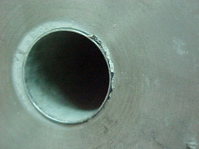
The choice of material should also take into account the corrosion mechanisms associated with the detail and technology. Crevice corrosion develops in narrow, partially closed crevices where water and chlorides can penetrate but oxygen has difficulty accessing, preventing the passive layer from renewing itself effectively. Stress corrosion requires the simultaneous presence of tensile stresses and specific environmental factors; it is unlikely in a typical building atmosphere, but in chloride-rich environments (e.g., indoor swimming pools, coastal areas) and under high internal stresses, it can become a design factor. Finally, in welded joints, attention must be paid to intergranular corrosion in the heat-affected zone, associated with the precipitation of chromium carbides in the range of 450-850°C; this risk is mitigated by the selection of appropriate grades (e.g., low-carbon or stabilized) and a carefully chosen welding procedure.
In practice, many disappointments with durability are not due to a “defect in stainless steel,” but to errors in the design and manufacturing process. Frequently cited causes include: insufficiently resistant grades selected for a given environment, poorly designed details that promote water retention or the formation of crevices, insufficient quality of manufacturing and surface treatment, as well as improper cleaning and operation. It should also be noted that if a serious corrosion problem is to occur, it usually manifests itself in the first years of operation. This reinforces the argument for verifying the environment and details before implementation, rather than “counting on stainless steel to forgive everything.”
Designing with corrosion in mind
Even a well-chosen grade may not meet expectations if the design and workmanship are conducive to the accumulation of moisture or contaminants. From a designer’s perspective, it is crucial to combine the selection of the grade with the right detail: ensuring water drainage, limiting “pockets” for deposits, and minimizing gaps where local deoxygenation and weakening of the passive layer may occur. In stainless steel structures, durability often “begins” in the detail drawing of the joint, rather than in the strength table.
Pro-durability details start with the geometry of the elements. Nominally horizontal sheets should be designed with a slope so that water does not remain on the surface. Where moisture accumulation cannot be avoided, drainage holes with a diameter that reduces the risk of clogging are designed. In open sections, the orientation of the profile is important; the same angle or channel can act as a “gutter” to retain water or as an element to facilitate drainage, depending on the setting. In tubular elements, it is worth deciding whether the profile will be closed and sealed, or whether ventilation and drainage are planned; intermediate solutions that allow water to enter but hinder its drainage are particularly risky.
Gaps are dangerous when they allow water and chlorides to penetrate while blocking the flow of oxygen. In such conditions, crevice corrosion can progress rapidly, even though the steel looks fine “on the open surface.” Therefore, solutions that limit the number of unclosed joints are preferred in detail, and if a gap is unavoidable, closing welds or high-quality seals are used. This applies in particular to areas where water remains for longer periods of time, for example, at supports, in depressions, under overlays, or near elements that obstruct free drainage.
Durability is also related to surface quality. An overly rough finish can promote the retention of contaminants, and the direction of grinding is important for water runoff. Manufacturing procedures are also important: the heat cycle of welding, the deposition of “foreign” iron particles, or insufficient removal of discoloration and spatter can impair corrosion resistance. Therefore, it is worth anticipating cleaning, surface treatment, and quality control requirements in critical areas at the design stage, especially if the structure is to operate in a harsh environment or will be visually exposed.
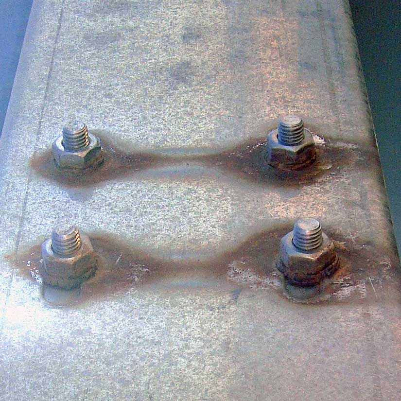
In places where other metals come into contact, the risk of galvanic corrosion must be considered, especially in the presence of electrolytes. In mechanical connections, it is recommended that screws be made of a more corrosion-resistant metal. When combining stainless steel with carbon steel, it is often effective to isolate the metals or design the coatings to limit electrolyte conduction. An unfavorable surface ratio is particularly dangerous in submerged conditions: a large stainless steel surface combined with a small carbon steel surface can accelerate the corrosion of the latter. In hybrid designs, it is therefore worth considering the arrangement of materials, rather than just a “single” detail.
Mechanical properties of stainless steels and their design implications
Designing for load-bearing capacity requires an understanding that stainless steel does not behave in the same way as typical carbon steel. The most important difference concerns the shape of the stress-strain curve: instead of a clear yield point and plastic “shelf,” stainless steel exhibits a more rounded curve and non-linearity even in a range that is almost perfectly elastic for carbon steel. In practice, this means that even at relatively low stresses, deformations greater than those resulting from linear elasticity may occur, which is important for the assessment of deflections, vibrations, and the tightness of connections.
For this reason, a conventional yield strength Rp0.2 is used in design, i.e., the stress causing a permanent deformation of 0.2%. At the same time, the proportionality limit is sometimes significantly lower and may only be about 40-70% of the Rp0.2 value. This is important in the context of the serviceability limit state: in slender elements with large spans or requiring high stiffness, it is not enough to “check the load-bearing capacity” – it is also necessary to reliably assess deformations and, if necessary, use material models that take into account non-linearity.
The mechanical properties of stainless steel can change significantly as a result of cold plastic working, which increases strength parameters, especially in austenitic steels. When designing thin-walled or cold-formed components, this means that the delivery condition, the forming process, and any welding near the deformed areas should be considered part of the “material model.” In tensile tests, it is therefore recommended that the load be applied in such a way as to ensure axiality and obtain the true stress-strain curve, without disturbances due to eccentricity or pre-stresses. This approach is particularly important when the design exploits properties resulting from strain hardening or when the elements are sensitive to deformation.
Limit states, coefficients, and calculation procedures according to Eurocode
In European design practice, stainless steel structures are calculated according to Eurocode logic, and the key starting point is working with limit states. A distinction is made between the ultimate limit state (ULS), the serviceability limit state (SLS), and the durability limit state (DLS). The latter is particularly natural for stainless steel, as durability often means not only maintaining load-bearing capacity, but also maintaining the required aesthetics and limiting local corrosion hotspots over time.
The verification condition in LBC boils down to comparing the calculated effects of interactions with the calculated load-bearing capacity of the element. The design load-bearing capacity is determined on the basis of the characteristic load-bearing capacity divided by a partial safety factor, the values of which are adopted in accordance with the part of Eurocode 3 concerning stainless steel and the rules for the design of joints. Consistency is important because a single design often combines rules from different parts of Eurocode 3: rules for bar elements, connection rules, and additional requirements resulting from the manufacturing technology.
In practice, the calculation process should be linked to the manufacturing assumptions. Stainless steel is sensitive to technological details, and its different material characteristics can affect the fulfillment of SGU. Therefore, it is good practice to agree on details, tolerances, and methods of surface protection and cleaning with the contractor at an early stage, before the cross-section and joints are “frozen” in the documentation.
Below is a webinar on the design of stainless steel structures (elements and connections) with references to Eurocode-type standards (material in English).
Sections
In the design of stainless steel members, many decisions come down to how the section will behave in the context of local instability. For this reason, sections are classified into classes 1–4, and the class determines both how the load-bearing capacity is checked and whether plastic calculations can be used. Even if the global load-bearing capacity of a bar is high, local loss of stability of slender walls may limit the use of the material.
In class 4 cross-sections, where slender walls may lose stability locally before reaching full material load-bearing capacity, the load-bearing capacity is determined using effective widths, i.e., a reduction in the contribution of compressed fragments to stress transfer. An additional nuance is the fact that the classification of the cross-section may vary along the length of the bar if the ratio of bending moment to axial force changes. This means that the designer should evaluate the cross-section in the most unfavorable conditions, and not just in one “representative” location.
The classification criteria are related to the maximum width-to-thickness ratios of individual walls. It is also worth remembering about usability: with greater slenderness, deformations and corrugations may appear, which do not necessarily mean a loss of load-bearing capacity, but may be visually or operationally unacceptable, especially in elements with an architectural function. Therefore, the selection of a cross-section is often a compromise between material economy and control of local deformations.
Bar design
Once the cross-section class and its cross-sectional load-bearing capacity have been determined, the bars are verified. In tensioned elements, the net cross-section in the area of the holes is typically the critical point, which is why the gross and net cross-sectional load-bearing capacity and possible block rupture are checked in bolted connections. For stainless steels, the procedure is similar to that for carbon steels, but requires consistent application of the appropriate material parameters and partial factors for the given grade, especially when cold-formed elements appear in the design.
Buckling is crucial in compressed elements. Design recommendations for stainless steels include buckling curves, which in some situations may be more conservative than those given in the standard, as tests have shown overly optimistic estimates for some cold-formed sections. Attention is also drawn to differences in buckling behavior between RHS/SHS columns made of ferritic steel and columns made of austenitic and duplex steel. In practice, this leads to a cautious selection of the buckling curve, and in the case of unusual cross-sections or technological solutions, to the use of test data or the manufacturer’s guidelines.
In bent elements, the problem of buckling is important, especially when the compressed flange is not laterally braced. In such cases, the buckling load capacity of the unbraced section is checked based on the buckling slenderness and critical moment. At the same time, the possibility of local instability of the walls under the action of a transverse force is checked, as slender webs may require a reduction in load capacity. If the shear force is significant, there is also an interaction between shear and bending, which must be considered in accordance with the appropriate procedure, rather than assuming that “since the cross-section is resistant to bending, shear is irrelevant.”
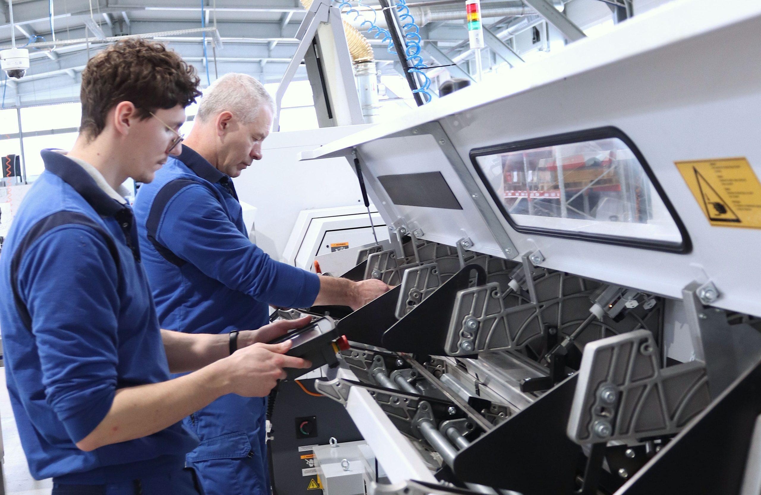
Joints, connections, and workmanship
Connections determine safety, durability, and installation costs, so in stainless steels, it is worth treating them as a “first-class” design element. In bolted connections, a distinction is made between thick and thin sheet metal connections, because in thin walls, deformations can limit the load-bearing capacity. In design recommendations for stainless steels, a wall thickness of 4 mm is often taken as the dividing line. It is good practice to use washers under the head and under the nut and to assume the load-bearing capacity of the connection as the lesser of the load-bearing capacity of the connected parts and the load-bearing capacity of the fasteners. Equally important are edge distances and bolt spacing, which affect the load-bearing capacity for compression, shear, block rupture, and the behavior of the wall near the holes.
In stainless steels, there is an additional operational aspect: some grades are susceptible to seizing and galling of threads under load and relative movement. If disassembly is anticipated in the future, the design and installation specifications should include measures to reduce seizing. In practice, this means controlling the tightening speed and avoiding “forceful tightening,” selecting appropriate anti-seize lubricants, and sometimes combining different types of screws and nuts to reduce the risk of sticking. Such recommendations have a design dimension: a seized connection is no longer “serviceable,” which is a real operational problem in long-life structures.
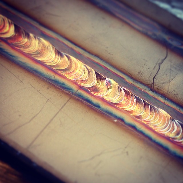
Welded connections require control of procedures because the heat cycle of welding affects the microstructure of all stainless steels, and this is particularly important in duplex steels. Qualified procedures, appropriate filler materials, and conscious weld shaping are necessary to achieve the required strength and geometry and to maintain corrosion resistance in the heat-affected zone. In cold-formed components, it is important to remember that welding can locally “negate” the effect of strain hardening, and in austenitic steels, greater welding deformations may occur than in carbon steels, which affects fit and aesthetics.
If the structure will be exposed to significant repetitive loads, fatigue must be considered. Welded joints are particularly sensitive due to stress concentrations and discontinuities, so it is recommended to apply fatigue assessment rules analogous to those for carbon steels for austenitic and duplex steels. The greatest effect is achieved by taking fatigue into account at the design stage, when the structural layout and details can be shaped to reduce notches and eccentricities. In practice, this means avoiding sudden changes in cross-section, limiting misalignment, paying attention to the quality of edges and surfaces, and avoiding unnecessary welding of secondary elements in sensitive areas, because even a “small” mounting bracket can initiate fatigue cracking.
Joints must also be designed with regard to workmanship and inspection. Assembly clearances, access to bolts and welds, tolerances, and welding technology requirements are important. The documentation should include provisions for inspecting the condition of components, cleaning, and possible maintenance work. Decisions that may seem “non-structural,” such as access to welds or the ability to wash and dry hard-to-reach areas, in practice determine durability and operating costs.
Design concerning fire conditions
The impact of fire in Eurocodes is treated as an exceptional situation, and the design must ensure that the structure retains its load-bearing function for the required exposure time. The general requirements are similar to those for carbon steels, but stainless steel has certain advantages in terms of material. The recommendations for stainless steels indicate that austenitic steel at temperatures above approximately 550°C retains a greater proportion of its strength compared to room temperature than carbon steel, and all grades of stainless steel retain greater stiffness throughout the entire range of thermal effects.
Fire calculations use strength and stiffness reduction factors depending on the grade group, as the properties of the material can vary significantly at elevated temperatures, depending on its chemical composition. In practice, this means that it is necessary to clearly assign the grade to the appropriate group and use the appropriate factors in verifying fire resistance. Even when stainless steel behaves favorably “by nature,” the fire resistance requirements of a structure may necessitate the use of passive fire protection measures; their selection should be coordinated with durability requirements (e.g., moisture resistance) and aesthetics if the element is exposed.
Designing stainless steel structures – summary
Designing stainless steel structures is not simply a matter of replacing carbon steel with a “more durable” material. A consistent approach is key, in which the selection of the grade is based on an assessment of the environment and is then supported by details that limit moisture accumulation and the formation of gaps. The mechanical consequences are equally important: the lack of a clear yield point and the tendency to strain hardening influence the course of calculations and the assessment of serviceability.
In strictly structural terms, stainless steel follows the same logic as Eurocodes, but requires greater attention in areas of local instability, cross-section classification, and bar stability. Joints and connections should be designed with durability and service in mind, and workmanship must protect the corrosion resistance of the material. When these elements “work together,” stainless steel allows for structures with high reliability, attractive aesthetics, and low maintenance costs throughout their life cycle.