GD&T in Practice
In many companies, GD&T (Geometric Dimensioning and Tolerancing) is often treated as a more difficult, more “formal” version of traditional drafting. When people see symbols, frames, and reference planes, they instinctively assume this is an additional layer of notation intended for the quality control or metrology departments. This is a misconception. GD&T was not created to make the drawing look more professional. It was created because simple dimensions with tolerances very quickly become insufficient when a part must not only be a specific size but also fit, align with other components, carry loads, and be unambiguously evaluated by the designer, manufacturer, and quality control. The authors of the Dimensioning and Tolerancing Handbook explain this from the ground up. When several people are working on a part – often in different locations and at different stages – everyone must have the same understanding of where to measure from, in which direction to measure, and where a given feature ends. This is where the role of GD&T begins.
The simplest and most important point is this: GD&T does not replace design. It organizes design requirements so that they are understandable, measurable, and unambiguous. The standard itself will not determine which surface should serve as the base or how tightly a hole needs to be controlled. That is still the designer’s job. GD&T, however, provides a language that allows these decisions to be recorded without ambiguity. The source states this very clearly: GD&T is not a creative design tool; it does not communicate the function of a part, nor does it tell you how to manufacture it or how to measure it; it is a language through which the designer translates design requirements into measurable specifications.
This article is based on the book Dimensioning and Tolerancing Handbook by Paul J. Drake Jr., specifically Chapter 5 – “Geometric Dimensioning and Tolerancing” – and, to a lesser extent, the chapters on mathematical definitions and differences between standards. The following content is only a general overview of the topic. For those interested in the topic, we recommend delving into the literature.
Why Does GD&T Exist at All?
It is best to start with the problem that GD&T solves. In classical dimensioning, it is easy to specify a distance, diameter, or thickness. It is harder to specify exactly what it means for a hole to be “in the right place,” for a surface to be “flat,” or for two axes to be “properly aligned with each other.” When a designer, a manufacturing engineer, and a quality control specialist look at the same part, and each understands the measurement starting point, reference direction, or method of determining the feature center slightly differently, disputes arise. The book illustrates this with a simple example of hole placement: everyone must agree on the start, direction, and end of the measurement. With high precision, even a small discrepancy leads to a difference between a usable part and scrap.
Here we see why a verbal description fails. A note like “make this surface really flat” sounds intuitive, but in practice, it is too vague. We still need to determine which surface it refers to, in which area, what exactly we mean by flatness, and how flat “really flat” is. The authors of the source address this problem almost verbatim and thus conclude that words are usually insufficient for such communication. GD&T was created as a language based on graphics, symbols, and mathematical rules precisely to eliminate this ambiguity.
This also explains why symbols are not mere decoration here. The book emphasizes that symbols have an advantage over textual descriptions for several reasons: they are independent of one’s native language, they mean the same thing to everyone, they are concise and can be placed close to the feature, and on top of that, they are easier to spot in a drawing. In practice, this means fewer “gut feeling” interpretations. If a tolerance frame is placed next to a specific surface or dimension, the design signal is local and unambiguous. This eliminates a common problem with traditional notes, which are formally present on the drawing but whose exact scope is unclear.
It’s also worth dispelling the popular myth right away that GD&T “naturally allows for larger tolerances” or “automatically reduces costs.” The source honestly states that GD&T itself provides neither larger nor smaller tolerances. It provides exactly as much leeway as the designer specifies. Its primary advantage is more fundamental: it ensures that everyone calculates and interprets geometry in the same way. Only on this basis can we reasonably discuss cost, process capability, or verification methods. Without this common foundation, even good numbers can lead to bad decisions.

Dimensions with tolerances and geometric control are not the same thing
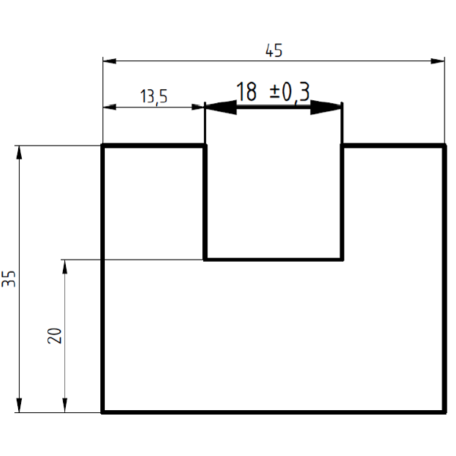
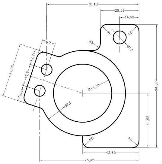
The most important practical distinction in GD&T concerns the difference between size and geometry. A dimension with a tolerance specifies what size is acceptable. It does not automatically tell us everything about the shape, orientation, or position of a surface. If a drawing shows only a width, diameter, or distance with a tolerance, we know how much material can exist between the dimension limits. We still do not know enough about whether this surface is flat, a straight axis, or a hole oriented perpendicular or aligned with the mounting base. Therefore, the classic “plus/minus” is insufficient where the function depends on geometry, not just size.
In practice, this is clearly illustrated by a simple example. A plate may have the correct length, width, and thickness, yet still be warped enough that it won’t seal properly with a gasket or rest stably on the mounting base. A hole may have the correct diameter, yet be offset, tilted, or distorted so much that a screw will enter with resistance or the assembly will not fit together at all.A shaft may fall within the diameter limits, but due to poor overall shape, it may not function correctly in the bore. This is precisely the area where geometric control becomes more important than the numerical value of the dimension itself.
GD&T organizes this world by separating the types of requirements. Form tolerances apply to the feature itself and do not refer to the datum system. The source explains this very clearly: form tolerances are not referenced to a datum system and do not control the shape relative to another feature or relative to a coordinate system built from other features. This is why flatness is different from perpendicularity. Flatness refers to the surface itself. Perpendicularity refers to a surface relative to a reference. This distinction is absolutely crucial, and without it, many drawings become either too restrictive or, conversely, functionally too weak.
This also yields an important design guideline. If the problem concerns only ensuring that the surface itself is not too wavy, it is usually not necessary to immediately build a full system of bases and positional tolerances. However, if the feature is to interact with other elements, the form alone is not sufficient. Orientation or location relative to bases is required. In practice, this means that a good specification does not start with the choice of a symbol, but with the question: is this about size, the shape of this single feature itself, or its relationship to the rest of the parts and the assembly?

Bases, base dimensions, and tolerance frames
One of the biggest mental leaps when transitioning from classical dimensioning to GD&T is understanding what datums really are. A datum is not simply “a surface from which someone measures with a caliper.” According to the source, a datum is a theoretically precise point, axis, or plane derived from an actual base feature. In turn, the datum system functions as a coordinate system located on the datum features of the part, and it is from this system that the position and orientation of other features are controlled. This is a very practical definition: a datum is not used to decorate a drawing, but to establish a common reference system for the functional geometry of the part.
In practice, a datum answers the question: relative to what should this feature be correct? If a part rests on a single plane during assembly, is aligned against a side wall, and is rotated through a hole or a second plane, then these features will typically become candidates for datums. The source also explains this in terms of degrees of freedom. The reference datum system reduces possible translations and rotations of the part. The primary datum restricts some movements, the secondary datum restricts others, and the third datum restricts the rest. Importantly, it is not always necessary to use all three. If the specification concerns only the orientation of one feature relative to another, fully “locking down” the entire system may be unnecessary.
The second pillar of the notation is reference dimensions. The book defines them as theoretically exact values describing the size, profile, orientation, or position of a feature or reference target. Their deviation is not recorded next to the dimension itself, but results from the corresponding geometric tolerance. This is important because it defies the intuition of many beginners. In classical drafting, the tolerance is placed next to the dimension. In GD&T, the basic dimension specifies where the feature should ideally be, and the tolerance frame specifies how much deviation from this ideal is permissible. This separates the nominal geometry from the zone of acceptable variation.
The heart of this notation is the tolerance zone. The source describes it very clearly: the first interval specifies the type of geometric characteristic being controlled, the second provides the tolerance value and any modifiers, and subsequent intervals contain references to the primary, secondary, and tertiary bases. What the frame does not contain is also important: the basic dimensions are outside of it. The frame can therefore be read from left to right like a sentence. In practice, this is extremely useful because it teaches the designer sequential thinking: what am I controlling, what is my tolerance zone, and relative to what. If someone cannot read their own frame as a complete sentence, it usually means that the notation is not yet refined.
Below is an English-language video titled GD&T Feature Control Frame Basics, which discusses how to read a tolerance frame and what it does not say.
Fundamental Rules and Four Levels of Control
The power of GD&T stems not only from the symbols but from the rules underlying the notation. The book reminds us that before moving on to detailed geometric tolerances, one must know several fundamental rules applicable to every drawing. For practitioners, four are the most important. First, every necessary dimension must have a tolerance. Second, the drawing must be complete and must not be “filled in” by scaling or guesswork. Third, dimensions must be selected based on function and assembly relationships, not on the drafter’s convenience. Fourth, the drawing should define the part without imposing a manufacturing method, unless such information is truly essential for engineering requirements. This last point neatly sums up the thesis of the entire article: GD&T specifies what the part must achieve, not how the manufacturer is to achieve it.
The principle of the free state is also very important. The source indicates that unless otherwise specified, dimensions and tolerances refer to parts in the free state. For rigid parts, this usually doesn’t cause much confusion. For thin-walled, rubber, or flexible components, however, it does. In practice, this means that the designer cannot assume that the part will settle into place during assembly if the drawing does not specify how to account for this in the requirements. This is not a metrological detail, but a real source of disputes between design and manufacturing.
Even more important for day-to-day work is the four-level control model for dimensional features. The book describes them explicitly: the first level controls size limits, the second level adds overall form, the third level orientation, and the fourth level location. The keyword here is “adds.” A higher level does not override a lower one, but builds upon it. This is a very engineering-oriented way of thinking. If a designer controls the position of a hole, this does not automatically mean that everything needed for form or orientation is taken care of “incidentally.” One must understand what a given tolerance actually covers and what it does not.
The source links this arrangement to the so-called Rule #1, i.e., the default principle of the perfect form envelope at maximum material condition in the ASME standard. In practice, the point is that for many-dimensional features, the size limit itself also carries a certain default form requirement that helps ensure fit. The authors emphasize that this rule makes sense, particularly where a mating fit and the ability to assemble parts are critical. At the same time, they note that the designer should consciously assess whether such an envelope is truly necessary, as there are situations where it becomes an unnecessary, cost-driving constraint.

Common mistakes, pitfalls, and false leads
The first common mistake is treating GD&T as a dictionary of symbols to be memorized. Yes, symbols are necessary, but mere knowledge of the icons guarantees nothing. One can know the symbols for position, perpendicularity, and flatness, yet still specify a part incorrectly if one does not understand what the functional reference is, what problem the feature is meant to solve, and what level of control is actually needed. The source even suggests teaching GD&T not as a drafting standard, but as a tool for communication and work across the entire company. This is an accurate approach because errors in tolerancing are rarely drafting errors; most often, they are errors in thinking about function and variability.
The second mistake is attempting to replace a geometric specification with a verbal description or a general remark. Sometimes this stems from haste, sometimes from the designer’s uncertainty. The problem is that words are not precise enough. “As close to perpendicular as possible,” “well aligned,” “align smoothly” sound like working notes, but they do not establish an unambiguous acceptance criterion. When a part starts causing problems, everyone will interpret such a note differently. GD&T clears this fog, but only when it is used in place of semi-formal comments, not alongside them as decoration.
The third mistake is an excess of bases and an excess of checks. It occurs especially among those who, after their first encounter with GD&T, try to “cover everything.” The effect is often the opposite of what was intended. If a feature requires only form control, adding bases introduces artificial relationships that the function does not require. If the third base no longer retains any significant degree of freedom, it can only complicate interpretation. The source states explicitly that a third-order constraint is often superfluous – that is, unnecessary – if there are no degrees of freedom left to constrain after the first two. Good practice, therefore, does not involve saturating the drawing to the maximum, but rather the selective choice of requirements.
The fourth mistake is mixing the responsibilities of design, manufacturing, and measurement. In many organizations, there is a temptation to tie the drawing to a specific machine or inspection method. Meanwhile, the fundamental rules in the book clearly indicate that the drawing should define the part without imposing manufacturing methods. Similarly, the authors note earlier that GD&T lacks the vocabulary to describe inspection or gaging methods. This does not mean that measurement is unimportant. On the contrary, requirements must be measurable. The point is simply not to confuse the criterion of conformance with the procedure for arriving at the result. First, you need to know what the part is supposed to achieve. Only then do you select the process and metrology.
When things get more advanced
At the basic level, it is enough to understand that GD&T organizes the relationship between function, geometry, and measurement. The more advanced level begins where interpretive issues arise. One of these concerns the standards themselves. The source notes that ISO and the American “dialect” of GD&T differ only slightly in many places, but in several areas, the differences are significant. A good example is the default approach to the envelope rule. In ASME, the default is a perfect form at the MMC according to Rule #1, whereas in ISO, the default principle is independence, and a special symbol must be used to explicitly include the envelope requirement. For practitioners, this is important information: one must not assume that two drawings written similarly mean the same thing if they operate under different standards systems.
The second level of advancement concerns the mathematical aspects of bases and tolerances. The source demonstrates that a system of bases can be treated as a coordinate system with six degrees of freedom, which are successively reduced by the primary, secondary, and tertiary bases. This is not theory for theory’s sake. This way of thinking is very helpful with more complex details, as it prevents the accidental addition of bases and better explains why a given base exists at all. If it does not account for any necessary translation or rotation, it likely adds no functional value. In complex assemblies, this discipline of thinking makes a huge difference.
GD&T in practice – summary
GD&T should be understood not as a set of symbols, but as a language for translating design requirements into unambiguous, measurable, and indisputable specifications. A classic dimension with a tolerance mainly refers to size. GD&T allows us to add what most often determines the function of real parts: form, orientation, and position relative to sensibly chosen bases. Therefore, a base is not a decoration but a reference system, and a tolerance frame is not a formality but a concise record of what we control, with what permissible deviation, and relative to what. The fundamental rules also remind us that a drawing is meant to define the part, not the manufacturing technology or a specific measurement method. In practice, the most important shift in thinking is simple: do not start with a symbol, but with the part’s function and the question of what geometry must truly be maintained for the part to function, fit, and be unambiguously evaluated. Then GD&T ceases to be a “decorative set of symbols” and becomes one of the main tools of engineering communication.