Fundamentals of technical drawings
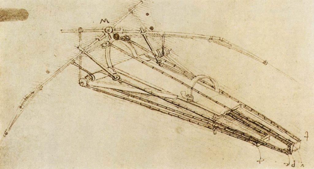
Table of Contents
Technical drawings, sometimes called engineering drawings, are illustrations used to communicate a wide variety of very often detailed information about the design, dimensions, and function of a product or system. Designers use them to communicate with engineers, manufacturers, and technicians. It doesn’t matter what we want to do because technical drawings contain all the instructions for turning an idea into reality.
Technical drawings are more structured than artistic drawings, which are more subjective and open to interpretation. This is because they use certain established conventions to ensure clarity and uniformity. The most important goal is to provide an accurate visual representation that everyone involved in the process can understand, regardless of language or location.
Why is it important to understand them?
There are surprisingly many essential professions. From engineers to various designers, manufacturers, drafters, and architects, many people interested in these critical industries understand the workings of technical drawings. Their knowledge does not need to be advanced to read them, making understanding them important for several reasons.
- Firstly, technical drawings serve as a universal language of design and engineering, fostering a global community of professionals. Using generally accepted rules for creating technical drawings minimizes misunderstandings, ensuring a shared understanding of designs across different cultures and languages.
- Secondly, they provide a blueprint, from the structure of a vast building to the appearance of a small precision part in a car should look like. So, it’s very easy to check the quality of production or assembly.
Those involved in machining or CNC machining must be able to read and interpret technical drawings. This enables machine operators and other workers to perform their tasks accurately and ensures that parts are made according to various specifications.
What are technical drawings?
A technical drawing is a detailed, graphic representation of a physical object or system. It is used for visual communication, providing information about an object’s dimensions, shape, materials, assembly, and function in a simple, standardized way. Technical drawings are designed to be universally understood by everyone involved in a project, regardless of location or language spoken. Professionals using technical drawings include engineers, architects, designers, and manufacturers.
They use certain conventions and symbols, thus ensuring that everyone can interpret the design similarly. These conventions include different types of lines, projections, dimensions, and annotations, which are the same all over the world according to various organizations such as:
- ISO (International Organization for Standardization)
- ANSI (American National Standards Institute)
History of technical drawings
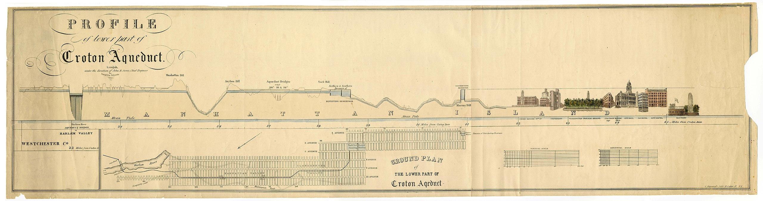
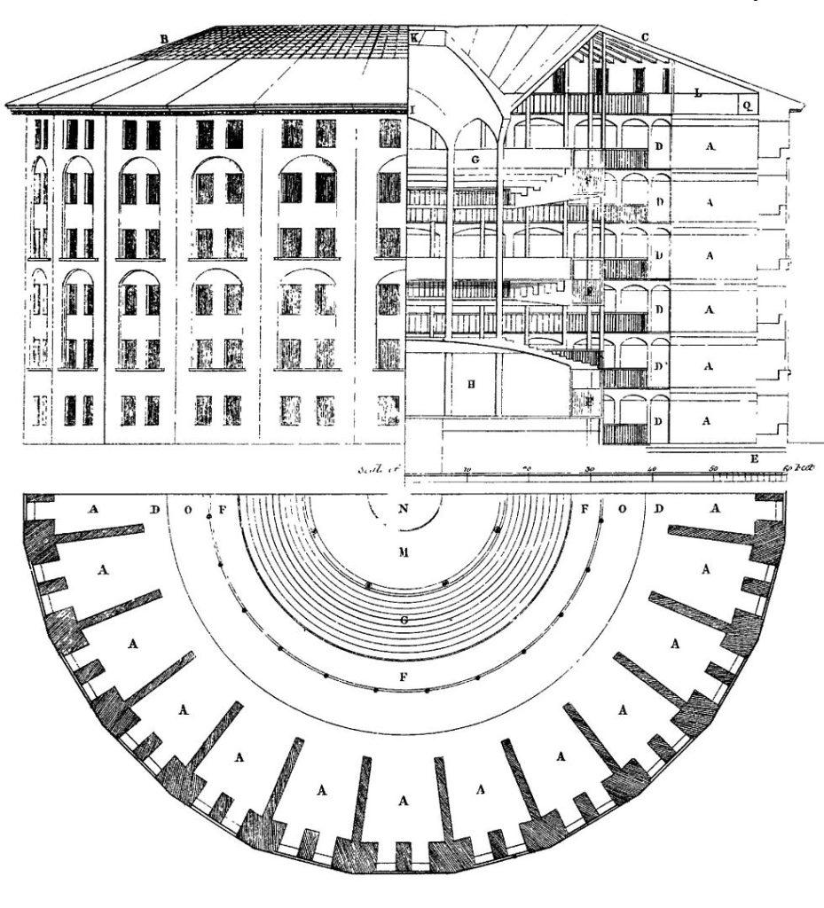
The history of technical drawings dates back to ancient civilizations. The Egyptians and Romans, for example, used simple sketches to communicate ideas for buildings, machinery, and tools. Early architects and drafters relied on primitive drawings to convey the construction details of various projects, such as the aqueducts that supplied water to Rome, the huge pyramids we still admire today, and weapons.
Although technical drawings had been used for hundreds and thousands of years, the first attempts to formalize their structure as we know it today were made only in the Renaissance. Leonardo da Vinci brilliantly used technical drawings and detailed diagrams to create many inventions and architectural designs. His sketches of flying machines, hydraulic systems, and anatomical studies are early examples of technical drawings.
Another critical period for the development of technical drawings was the Industrial Revolution in the 19th century. This is because they were used to improve mass production. A growing demand for standard drawings and plans accompanied the development of factories and machines. New symbols, scales, and formats for drawing diagrams, plans, and schematics were systematically created. This facilitated communication and cooperation in different areas, regions, and countries.
Examining Leonardo da Vinci’s technical drawings and innovations, the English documentary “Decoding da Vinci” highlights his influence on contemporary engineering. You can watch the entire documentary below.
Primary objectives of technical drawings
An essential purpose of technical drawings is to convey detailed information about the structure, dimensions, or assembly so that they can be done precisely and unambiguously. Today’s popularity of technical drawings can be attributed to their role in engineering. Some examples of their purposes include:
- Accurately depicting dimensions and shapes – enables a high degree of precision in building houses, creating machines, or manufacturing parts. Precise descriptions are essential in many fields, such as architecture, electronics, CNC turning, and metal machining, where the slightest errors affect functionality.
- Creating functional and aesthetically pleasing designs – the most important thing in architecture is that buildings and spaces are both functional and aesthetically pleasing, meeting all the client’s needs.
- Enabling quality control – inspectors can verify that the building meets all requirements and tolerances by using technical drawings as a reference. This is used in precision manufacturing, as meeting these tolerances is critical to ensuring high quality.
- Meeting standards and regulations – many technical professionals, such as architects, engineers, and designers, must meet specific standards, tolerances, building codes, and safety standards.
- Standardization – using generally accepted formats and symbols allows people from different backgrounds and industries to work together effectively.
Types of technical drawings
Nowadays, there are several types of technical drawings, each with its unique application. These types include assembly, executive, and summary drawings, each serving a specific purpose and used in various industries.
- Assembly – an assembly drawing shows the mutual position, shape, and cooperation of all the subassemblies of the parts being put together. Each assembly and part has specific numbers described in a special plate. The drawing should include all the parts of a product. This is why we use axonometric projection and sectional views in technical drawings. They are used in industries such as automotive, aerospace, and electronics.
- Executive – executive drawings are called detail drawings, which contain the information necessary to make them. These include the type of material, how the detail is to be made, the required cross-sections, and all projections of the object. Each detailed drawing has a table containing additional data, such as the drawing number and pitch size. Each part on an executive drawing must have the same number as the drawing.
- Summary drawing – this is the assembly drawing of the product with additional information and dimensions necessary for the individual details shown.
- Architectural and construction drawing – this is a technical drawing that shows a building or part of a building. It is the basis for the execution of construction work. It is created by a draftsman under the supervision of an architect, architectural technician, or civil engineer. It is part of every construction project. Most often, it shows a projection, cross-section, or elevation of a building. We must deal with different scales, details, and drawing methods depending on the production stage. A generally accepted rule is that the essential scales for showing cross-sections, floor plans, and elevation views are 1:50 or 1:100. In the detailed design, larger scales show the construction details.
- Installation – it shows the various activities and necessary information for installing the device. As a rule, they do not include the object’s dimensions, but sometimes, we can come across drawings with overall dimensions.
- Schematic – this type of technical drawing in which the most important thing is to show the principles of operation of the device, installation, or system. This type of drawing does not show the relationship in space, nor does it provide information about the dimensions of objects. Instead, it shows the logical and functional relationships of the object. They are shown in a simple, symbolic way.
- Operational – this technical drawing shows the details with additional applied data necessary to perform one technological procedure.
- Pictorial – reproduces in a pictorial manner the most essential features of the object.
- Mounting – a technical drawing that shows the arrangement of each installation component and how they are to be connected.
Each type of technical drawing has its own special use. Some are used in architecture and for the construction of monumental buildings, and others in the production of small parts, which are often components of a larger whole. Technical drawings make it possible to show processes that may look complicated at first glance in a simple way.
Detail drawings are especially important in the production of prototypes, where precision is crucial to a project’s success. Contact us if you’re looking for a company that creates details based on technical drawings. We are experts in the serial production of precision metal parts on powerful automatic CNC machines. The components we produce are delivered to customers throughout Europe and even beyond.
Elements of a technical drawing
Every technical drawing must include several key elements. This ensures clear, accurate, and easy-to-understand information. Over many centuries, these elements have undergone various attempts at standardization to maintain consistency and clarity.
Lines and line types
Every technical drawing includes different types of lines that are used to convey important information. The following are selected types of lines and their uses:
- Thick continuous lines – visible edges of objects.
- Thin continuous lines – used as dimension, projection, and reference lines.
- Dashed lines – edges or elements that are not visible in a given perspective.
- Chain lines – indicating centerlines or axes of symmetry.
Each type of line is very important to convey correct information. The most important thing is to use it according to established standards.
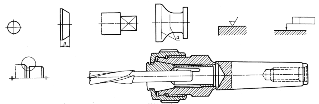
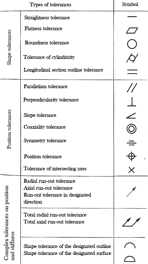
Symbols and designations
Technical drawings rely on many symbols and designations to simplify information. Technical drawing symbols represent anything from geometric features to surface finishes or tolerances. Some commonly used symbols are:
- Welding symbols – the type and location of welds needed to join components.
- Geometric tolerance symbols – defining allowable deviations from ideal geometry.
- Material symbols – different materials, such as steel, plastic or wood.
- Surface finish symbols – indicate the required texture or surface finish after machining or fabrication.
Symbols must be interpreted correctly to fully understand a part or system’s technical requirements. For example, in CNC milling, surface finish symbols help to understand how smooth or rough a part’s surface should be.
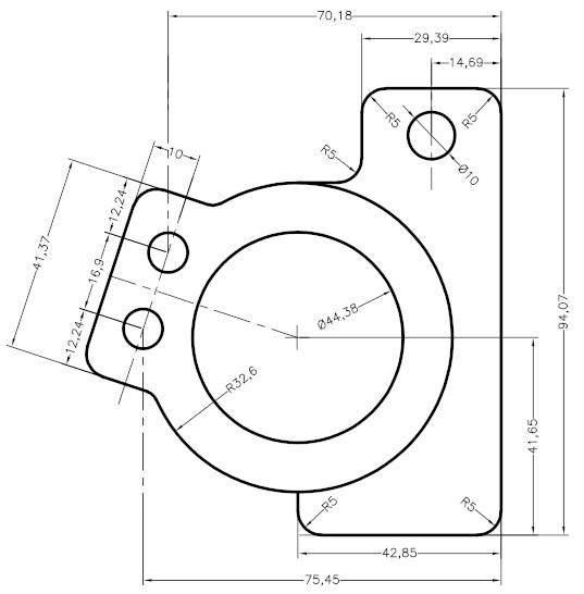
Dimensions and tolerances
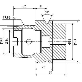
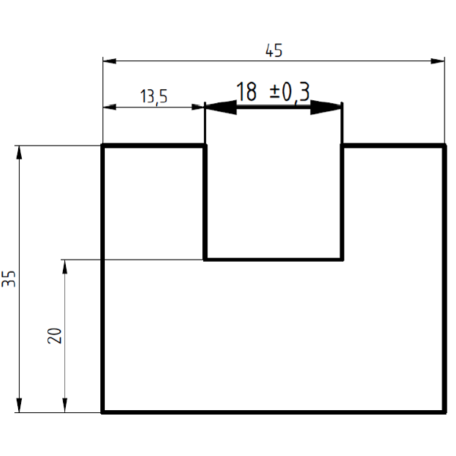
Dimensions are of paramount importance for any technical drawing. This is because they define parts’ size, shape, and position on a part. They typically include linear dimensions, diameters, radii, and angles. Most technical drawings show dimensions in millimeters or inches, depending on the industry and country.
Tolerances, on the other hand, define the permissible deviation of part dimensions. They are used because manufacturing processes are never perfect. Tolerances take into account these small deviations. Parts that must fit together precisely, such as engine components, often have tighter tolerances, so the manufactured part must be more accurate.
A manufactured part that does not exceed tolerances is crucial to ensure everything works as intended. A slight deviation from the required dimensions can cause components to fail or not fit properly.
Scale and proportion
Technical drawings often depict something larger or smaller than the drawing itself. To accurately represent these objects, drawings are created using scale. It indicates the ratio between the dimensions of the drawing and the actual dimensions of the object.
For example, drawing to a scale of 1:100 means that 1 unit of a drawing equals 100 units in reality. For instance, if the length of a wall in a drawing is 5 cm, it is 500 cm or 5 meters. Conversely, a scale of 2:1 indicates that the sketch of an object is twice as large. Using scale allows large structures, such as buildings, and small parts, such as a screw, to be represented on a reasonable size of paper.
Reading and interpreting technical drawings
Technical drawings can be read once we know their basic elements, which include dimensions, views, lines, and symbols. At the beginning of learning, they may seem overwhelming. Still, with time, everyone is sure to be able to understand them.
How to read technical drawings?
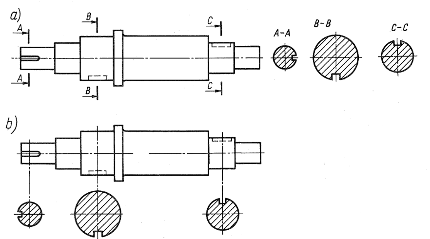
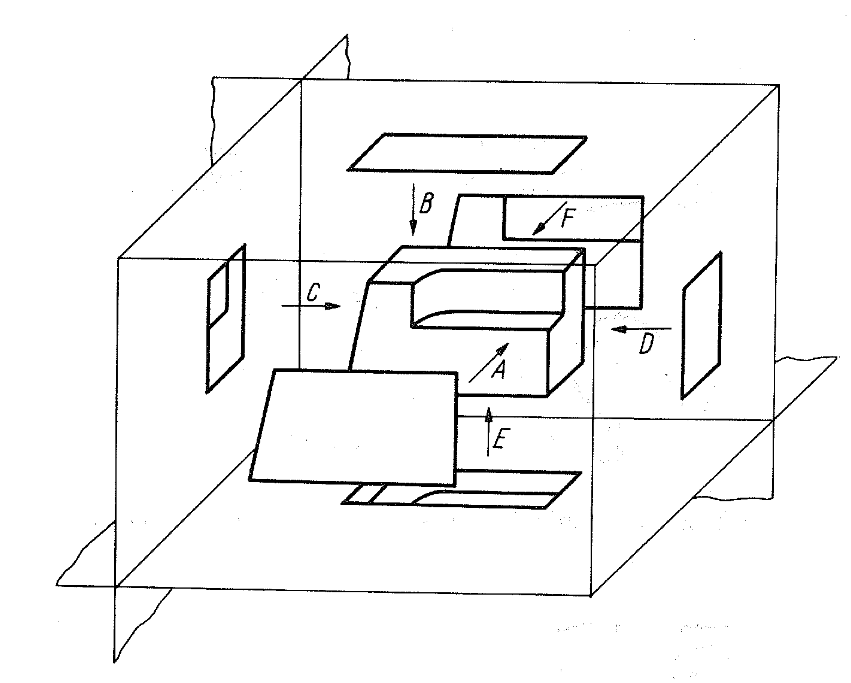
The first step in reading a technical drawing is to identify the different projections of an object. There are three main projections:
- Top view
- Side view
- Front view
These projections clearly show the object’s dimensions and shape. Once you know them, the next step is to check the dimensions. We do this because they give key information about the size and placement of the parts on the part. You should also carefully check the tolerances associated with each dimension to understand the allowable deviations.
A thorough understanding of tolerances and dimensions will help ensure that parts are produced within acceptable limits. For example, a shaft must fit into a hole to a certain extent – it must be tight enough. Misinterpreting tolerances can cause the part to not work as intended or fail.
Understanding symbols and markings
Once we recognize the projections and dimensions of our engineering drawing, it is important to find the symbols and notations. These are key to understanding the various requirements that may be assumed in a project. For example, welding symbols will tell us where and what kind of weld to use, and dimensioning and tolerance symbols will give us information on allowable deviations from given dimensions.
Understanding the meaning of these symbols is important because they provide important information about construction, assembly, and inspection.
Tools for creating technical drawings
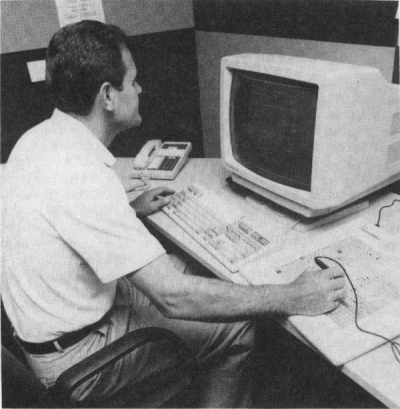
Before software for designing technical drawings on a computer, known as CAD (Computer-Aided Design), technical drawings were created using manual drafting tools. These included pencils, rulers, protractors, and drawing boards. Computer programs have almost entirely replaced hand drafting. To this day, it remains an essential skill for students learning the principles of technical drawing.
Traditional drafting requires great accuracy, a steady hand, a sharp eye, and precision. Those who design technical drawings must be skilled in using these tools to create accurate, neat drawings with correct lines, angles, and dimensions.
Introduction to CAD software
Today, to create various types of technical drawings, we use a variety of computer programs that have revolutionized their creation and sharing. Some of the most popular programs are AutoCAD, SolidWorks, and CATIA. Engineers and designers can create highly detailed 2D and 3D models for parts and other systems.
- AutoCAD is one of the best-known CAD tools. It is used to create technical drawings in 2D space and 3D models. It is used in industries such as architecture, engineering, and CNC machining. The program is very flexible and easy to configure, making it the basis for 2D and 3D design.
- SolidWorks is another popular CAD tool. It is used to design technical drawings and for 3D parametric modeling. It has an intuitive interface and many simulation creation capabilities, so it is widely used in many industries today.
- CATIA is an advanced CAD program used for complex and large-scale projects. It is the best solution in industries such as aerospace and automotive, where complex 3D models and simulations are crucial to ensure excellent accuracy.
CAD software offers many advantages over manual drafting, including modifying designs quickly, automatically generating multiple views, and rendering 3D models. As a result, CAD has become a standard method in most industries, significantly improving the efficiency and accuracy of the design process.
Fundamentals of technical drawings – summary
Technical drawings are the backbone of engineering, manufacturing, and construction. They communicate complex information about size, shape, materials, and assembly. Understanding how technical drawings work, how to read and interpret them, and how they can be created is worthwhile because it is a very interesting topic.
Technology has developed to the point where advanced tools like CAD software have been created. These tools preserve the basic ideas that have guided the creation of technical drawings for several centuries while allowing drawings to be created quickly and accurately. Becoming proficient in using technical drawings is essential for efficient work and implementing new ideas.
Technical drawings have many norms and standards that vary from industry to industry and region to region. Understanding these standards is essential to ensure project compliance and consistency, especially in international collaboration.
This knowledge is helpful in various fields, including architecture, building, and construction. At Sabner, we manufacture small, precise parts, so we greatly emphasize understanding technical drawings.