Why Does Metal Break? An Introduction to Failure Analysis
A crack in a metal component is almost never merely a sign of damage. For an engineer, it is a trace of the history of loading, geometry, material, manufacturing technology, and operating conditions. The same shaft may crack because it was overloaded once, because a fatigue crack had been developing in it for months, or because, at low temperatures and under severe stress, the material entered a brittle fracture regime. If this history is not reconstructed, it is easy to confuse the effect with the cause. This is precisely why failure analysis does not involve matching the first intuition to the damaged part, but rather reconstructing the course of the failure.
This approach is important in practice because the quality of the diagnosis determines whether the next version of the component will actually be better. If someone sees a crack and immediately concludes that the material was too weak, they may pointlessly increase the hardness, thereby further increasing susceptibility to brittle fracture. If, on the other hand, they see a shiny fracture surface and conclude that it was merely due to overloading, they may overlook the fact that the vast majority of the component’s service life was spent on the propagation of a fatigue crack originating from a notch, a machining scratch, or a manufacturing defect. In failure analysis, therefore, the most important thing is not to quickly label the phenomenon, but to understand where the crack originated, how it propagated, and why the operating conditions allowed it to reach its final stage.
This article is based on Donald J. Wulpi’s Understanding How Components Fail, primarily the chapters on failure analysis techniques, questions asked during fracture examination, and on brittle, ductile, and fatigue fractures, as well as the fundamentals of fracture mechanics. The content below is only a general overview of the topic. For those interested in the topic, we recommend delving into the literature.
Failure analysis begins with discipline, not with a hypothesis
In classic workshop practice, there is often a temptation to say after a first glance: “it broke due to fatigue” or “it cracked because it was brittle.” Wulpi takes the opposite approach. The most important first step in analysis is essentially to do nothing in the sense of irreversible actions, but rather to study the traces, examine the details, ask detailed questions about the part, the machine, and the circumstances of the failure, and keep accurate notes. This may seem minor, but it makes engineering sense. Any cutting, grinding, or drilling performed too early can destroy a trace that would later be crucial for identifying the fracture’s source.
A methodical approach follows a logical sequence. First, background data is collected and samples are selected; then a preliminary visual inspection and documentation are performed, followed by non-destructive testing, mechanical testing, macroscopic and microscopic analysis, preparation of metallographic sections, metallographic examination, identification of the failure mechanism, chemical analysis, and in more difficult cases, also analysis using fracture mechanics and tests under conditions simulating actual operation. Only at the end is all the evidence compiled into a coherent hypothesis of the failure sequence and translated into conclusions and recommendations. This sequence prevents a situation where the result of a single test is interpreted without the context of the others.
Three rules govern the entire analysis. First, the crack initiation point must be located. Second, one must not carelessly assemble the fracture halves, because fracture surfaces are delicate and can be easily damaged even by touch, corrosion, or careless transport. Third, destructive testing is performed only after everything that can be determined has been extracted from the part in its original state. In practice, this boils down to a simple rule: documentation and visual inspection first, then intervention. This is particularly important in the case of fatigue fractures, where subtle traces of the propagation direction and the initiation point are often more valuable than the subsequent result of a single hardness test.
This discipline has another purpose. Damage analysis does not examine only the material itself. It examines the stresses, strength, geometry, and environment in which the specimen was located. Wulpi emphasizes that a metal part does not simply break at the weakest point, as is naively understood. It will fracture where the local stress first exceeds the material’s local strength. That is why it is not enough to ask whether the steel was of good quality. One must also consider geometric features, loads, residual stresses, temperature, surface condition, and service history.
How an engineer reconstructs the history of a fracture
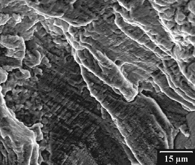
The most important witness is the fracture surface itself. It reveals the mode of failure, the source of the fracture, the direction of the crack, and whether the fracture developed all at once or in stages. Wulpi clearly warns against hasty conclusions based on a single fragment. The entire section must be examined, because only by comparing all areas of the fracture can one distinguish the initiation zone, the crack growth zone, and the final rupture zone. This is why low magnifications of a dozen or several dozen times are so useful. In many cases, the most important information is not found in high SEM magnification, but in the overall image of the fracture.
The second step is to ask whether the fracture location is normal. The author provides a simple but very useful rule: every part has typical locations of expected failure. For metal components, these are often geometric stress concentrators, such as the first threaded turn of a screw, the radius of a shaft transition, the root of a tooth, or the area around a hole. If the part fractured exactly there, the analysis follows the stress–strength relationship. If it fractured in an atypical location, one must look for additional weakening: a local material defect, surface damage, overheating, corrosion, an assembly error, or a load that the operating model did not previously account for.
The third step involves asking the right questions about operating conditions. Wulpi broadly categorizes them: regarding the fracture itself, the part’s surface, geometry and design, the manufacturing process, material properties, the relationship between residual and working stresses, the influence of adjacent parts, assembly, operation, and the environment. In practice, this is a very good investigative roadmap. When a shaft breaks, it is not enough to check the steel and hardness. You also need to ask about misalignment, play, contact marks, overloads, lubrication, heat treatment, grinding marks, temperature, and corrosion. Very often, the root cause lies not in the fracture itself, but in what led to a local increase in stress or a decrease in the material’s strength.
This approach also clarifies thinking about complex failures. If there are several cracked components in a system, this does not necessarily mean that they all failed independently. Wulpi points out that the damaged part may simply be a victim of a primary failure elsewhere in the system. A loose screw connection can lead to overloading of an adjacent part. A seizure can alter the load on a shaft. A secondary fracture can easily be confused with the primary one if one looks only at the number of damaged components rather than the chronology. This is precisely why the thesis of this article is so practical: to understand a failure, one must reconstruct the history of the fracture, not just examine the final result.
Below is an English-language video titled The role of fractography in failure analysis 1_2 explaining the role of fractography in failure analysis, how to interpret fracture surfaces, and how to distinguish between fracture mechanisms.
Brittle fracture
Brittle fracture is dangerous for practitioners because it can appear as a failure without warning. The key feature is simple: there is no clear, macroscopic plastic deformation in the area of the brittle fracture. The component does not give many warning signs in the form of a neck, significant bending, or local plastic deformation. From the user’s perspective, the part often simply breaks suddenly. This is why brittle failure is so treacherous in load-bearing structures and highly stressed components.
Macroscopically, a brittle fracture is often bright, shiny, and more “crystalline” in appearance than a ductile fracture, but the geometry of the marks is more important than the luster. Many brittle fractures are characterized by chevron marks, i.e., herringbone- or arrow-shaped marks that point backward toward the initiation point. This is an extremely useful interpretive tool. If such a pattern is visible on the fracture surface of a shaft or plate, one can not only determine the direction of crack propagation but also narrow down the area where the search for a notch, welding defect, pre-existing crack, or corrosion damage should begin. In the case of a brittle fracture, the fracture plane usually lies perpendicular to the principal tensile stress at that location.
The most important interpretive pitfall is that brittle fracture is not exclusive to materials that are inherently brittle. Wulpi strongly emphasizes that even steels typically considered ductile can fracture in a completely brittle manner under certain conditions. This is facilitated by a combination of factors, including stress concentration, high tensile stresses or unfavorable residual stresses, relatively low temperature, and a susceptible material. In practice, this means that the statement “it was ordinary structural steel” does not settle the matter. If the component had a sharp notch, an unfavorable stress state, and was subjected to cold working, the ductility listed in the catalog may not translate into a ductile fracture in the actual part.
The design consequences are clear. If an engineer improves strength by increasing hardness while leaving sharp radii, introduces residual stresses after machining, and fails to control operating temperature, they may shift the system toward brittle failure. In such cases, a stronger material is not always the solution. Larger transition radii, better surface finish, reduction of welding defects, control of residual stresses, and selection of steel with better resistance to brittle fracture under given conditions often prove more effective.
Ductile Fracture
Ductile fracture follows a completely different logic. It results from applying too much force to a metal capable of plastic deformation before breaking. Therefore, the first sign here is usually not the fracture itself, but an earlier change in shape. During tensile testing, necking, local elongation, and distinct plastic deformation occur. Compared to brittle fracture, this type of failure rarely occurs suddenly, as the specimen itself indicates beforehand that it has exceeded the safe operating range.
Macroscopically, a ductile fracture is usually dull and fibrous. A classic example is the cup-and-cone fracture, observed in tensile specimens. First, microvacuoles develop in the center of the narrowed cross-section, then the fracture propagates toward the surface, and finally changes direction toward the shear planes at an angle of about 45 degrees, forming the so-called shear lip. This is important in practice because the final fracture zone in ductile fracture indicates the final stage of failure and often clearly reveals the local stress state.
Microscopically, the mechanism of ductile failure involves the coalescence of microvoids, rather than the abrupt separation of crystals as in a classic brittle fracture. This leads to an important interpretive implication: ductile fracture is more closely associated with the dominance of shear and plastic flow of the material. From a practical standpoint, such a fracture often indicates that the component was not so much defective as it was simply in an overloaded state or had insufficient strength margin for the actual loading conditions. This may result from a single overload, incorrect assembly, an inappropriate cross-section, or loss of material due to wear or corrosion.
Here, too, a pitfall lurks. Visible large deformation does not yet prove that the entire failure was ductile from start to finish. Wulpi notes that many actual failures are mixed. Some may begin as fatigue or brittle, and only the final zone of rapid rupture is ductile. In practice, this means that one must not classify the entire failure based solely on the final zone. One must distinguish the mechanism of crack initiation and propagation from the mechanism of the final rupture of the remaining cross-section.
Fatigue cracking
From the perspective of machine operation, fatigue cracking is the most insidious, as it can develop during normal operation without any spectacular overload. Wulpi defines it as a phenomenon leading to fracture under the action of repetitive or varying stresses, the maximum of which may be lower than the material’s tensile strength. This is precisely what makes fatigue so treacherous. The user does not see a single undesirable event. The part continues to function, while minor structural changes accumulate until a microcrack forms.
The logic of fatigue is best divided into three stages. In the initiation stage, repetitive shear stresses cause irreversible changes in the crystal structure and lead to the formation of a very small crack. In the propagation stage, the direction of the crack changes, and the crack grows essentially perpendicular to the tensile component. In the third stage, the remaining cross-section becomes so small that the final rupture occurs under one of the subsequent loads. This final rupture is no longer fatigue-induced in the strict sense. It may be brittle, ductile, or mixed. This is very important for an analyst because most of a component’s life is usually spent in the initiation and growth zones, not at the moment of final failure.
Macroscopically, a fatigue fracture often shows little deformation. This is natural because initiation does not require a high stress exceeding the yield strength of the entire cross-section. A good counterexample is a paperclip or a wire hanger, which can be broken after a few strong bends. This is also fatigue, only low-cycle, and with distinct deformation. In typical machine parts, the absence of significant plastic deformation and the presence of crack propagation traces at the fracture surface are more characteristic.
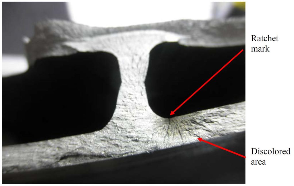
The most important macroscopic features include beachmarks and ratchet marks. Beachmarks are macroscopic bands showing successive positions of the fracture front, something like large crack growth increments. Ratchet marks, on the other hand, are very useful for identifying multiple initiation points, as they form between adjacent cracks growing from several sources and usually run more or less perpendicular to the surface from which the fatigue originated. In rollers, they have a radial character. Thanks to them, one can not only find the source but also determine whether the problem began at a single point or along the entire circumference, for example, from multiple notches or machining marks.
At the microscopic level, the most characteristic features are striations, i.e., very fine lines marking successive positions of the crack tip. Wulpi, however, points out something important for practical application: the absence of striations does not rule out a fatigue diagnosis. In very hard materials or under certain conditions, the surface may not show them clearly. This is a valuable caution against excessive reliance on a single textbook sign. Failure analysis works well when it combines macro and micro views, part geometry, and operating conditions, rather than when it searches for a single fracture icon.
When fractography alone is not enough
In simpler cases, a good reconstruction of the source, growth direction, and operating conditions is sufficient. In more complex cases, fracture mechanics comes into play. Wulpi proposes a very useful conceptual model here: a structure’s resistance to fracture depends on three interrelated factors – namely, the applied stress, the crack length, and the material’s resistance to crack propagation, or toughness. This organizes our thinking better than simply asking whether the material was strong enough. A material can be strong in terms of its yield strength and yet still be dangerous if a crack of significant length already exists.
This is precisely what fracture mechanics contributes, as it does not merely consider the nominal stress in an undamaged cross-section but accounts for the presence of a crack as a local stress concentrator. In a linear-elastic framework, it is assumed that cracks and discontinuities are inherently present, and the analysis focuses on when such a defect becomes critical. For a failure analyst, this raises practical questions: what was the crack length when it entered the unstable propagation range, could the part still operate safely, and what level of NDT inspection or maintenance does a given type of structure require?
Fracture mechanics does not replace classical damage analysis; rather, it complements it. Fractography tells us where and how the fracture occurred. Metallography and materials testing tell us what we were dealing with. Fracture mechanics allows us to assess whether the crack size and stress state were already critical. This is usually the point at which damage analysis moves from describing the damage to a level where we can predict when a similar failure will become inevitable.
Why Does Metal Break? An Introduction to Damage Analysis – Summary
Metal does not fracture on its own. It fractures when, at a specific location, a specific combination of stress history, geometry, material, manufacturing, and environment leads to the local fracture resistance being exceeded. Therefore, failure analysis is not about guessing the mechanism based on first impressions, but rather methodically reconstructing the fracture path. First, evidence must be secured, the fracture examined, and the source identified. Then, the evidence must be correlated with questions regarding design, fabrication, and operating conditions. Only then can the three basic paths of interpretation be meaningfully distinguished. Brittle fracture produces little deformation and progresses rapidly, often involving notching, tensile loading, and low temperatures. Ductile fracture shows prior plastic deformation and usually indicates overloading or insufficient safety margin. Fatigue fracture develops in stages, often during normal operation, and its essence is that the vast majority of the component’s service life is spent on crack initiation and growth before final failure occurs. In more complex cases, this picture is completed by fracture mechanics, which reduces the problem to the relationship between stress, crack length, and the material’s resistance to crack propagation. It is precisely this way of thinking that allows us not only to describe that a component has fractured, but to understand why it fractured and what needs to be changed so that the next one does not fracture in the same way.