Assembly drawing
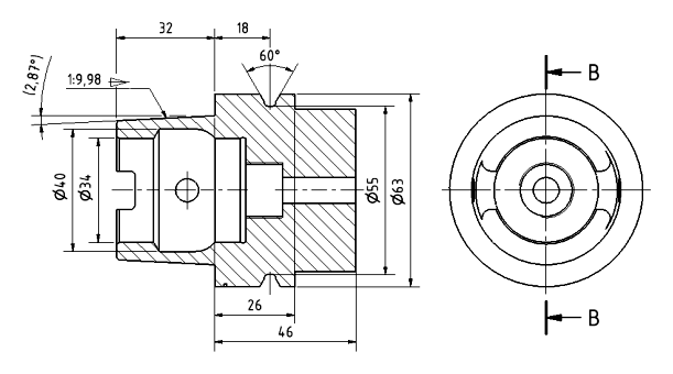
Table of contents
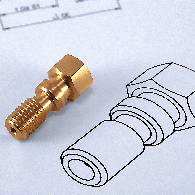
If Leonardo da Vinci were designing his machines today, he would probably have to contend with ISO standards and a number of engineering conventions. Technical drawing is the language used by designers – precise, with no room for understatement. Among its various forms, assembly drawing has a special role – it is a kind of “city plan” for mechanisms, devices, and structures.
Imagine a watchmaker trying to assemble a precise mechanism based on imagination alone. Chaos. Without a clear drawing indicating where every screw and cog fits, even the most advanced technology remains a pile of useless parts. That’s why assembly drawing is one of the pillars of technical documentation – it allows assembly and analysis of the structure, its operation, and possible modifications.
Assembly drawing vs. other types of technical drawings
An assembly drawing is one of the key elements of technical documentation, which makes it possible to precisely define the mutual position and cooperation of the various elements of a structure. To fully understand its role, it is worth distinguishing between it and other types of technical drawings used in engineering.
Construction documentation includes several main types of drawings, each of which performs a different function in the design, manufacturing, and assembly process. Among the most important are:
- Overview drawing – shows an object in simplified form, often from an axonometric perspective, without technical dimensions. It is used for conceptual and presentation purposes.
- Executive drawing – contains all the necessary information for the manufacture of a single component, including its exact dimensions, tolerances, surface roughness, and any technological requirements.
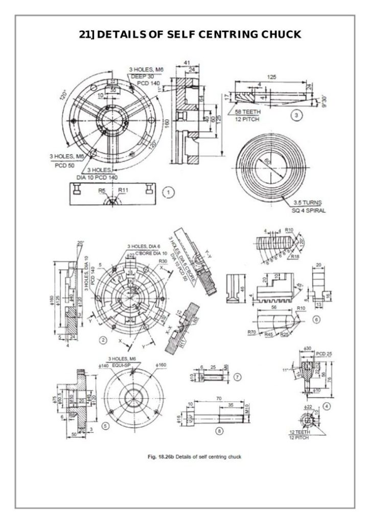
- Assembly drawing – describes how the elements are connected and the order of assembly, often containing additional assembly instructions.
- Installation drawing – shows the arrangement of components in a larger system, such as in plumbing or electrical systems.
Specifics of assembly drawing
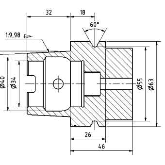
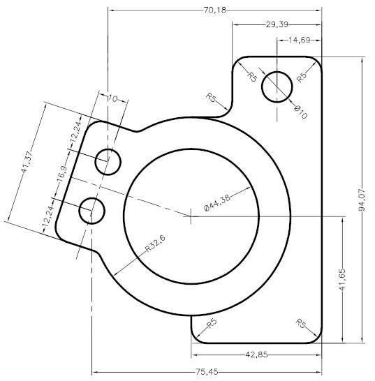
The assembly drawing differs from the above technical drawings primarily in the scope of the information it contains. Its main function is to depict the entire structure, taking into account all the components, their position relative to each other,, and how they work together. Unlike an executive drawing, it does not include detailed dimensions of individual details; it is limited to the assembly’s overall dimensions and characteristic dimensions.
Key features of a technical drawing are, for example:
- Representation of the assembly or the entire device in appropriately selected views and sections,
- Numbering and designation of individual parts,
- List of parts (so-called component specifications),
- Limited use of dimensioning – only general and overall dimensions,
- Lack of detailed tolerances and technological data are included in manufacturing drawings.
Thanks to these features, the assembly drawing is the primary source of information for manufacturing and assembly departments and serves as reference documentation in quality control and equipment service processes.
Construction of the assembly drawing
The assembly drawing, one of the key elements of technical documentation, must be made in accordance with certain norms and standards. A correct drawing clearly defines the mutual position and cooperation of the various elements of the structure.
In order to fulfill its functions, the assembly drawing should contain the following elements:
- Projections and sections – depending on the complexity of the structure, the assembly drawing may include:
- Main views (e.g., front view, top view, side view),
- Cross-sections, which help show the internal structure of the assembly,
- Detailed views, if necessary, should include small details.
- Part numbering – each part of the product shall be identified with a unique number that corresponds to the item in the parts list. These numbers shall be placed in the form of markings on the drawing, connected to the corresponding components by thin reference lines ending with a dot.
- Overall dimensions – as a rule, the assembly drawing does not give detailed dimensions of individual components. The exceptions are general dimensions relevant to assembly and external interfaces.
- Drawing plate – according to PN-EN ISO 7200:2007, this plate should be located in the lower right corner of the sheet. It should contain such information as:
- Number and name of the drawing,
- Name of the company or institution preparing the documentation,
- The scale of the drawing,
- Data of the person responsible for the development and approval of the document,
- Designation of the projection standard.
- Parts list (component specification) – a listing of the components of an assembly placed above the drawing plate or on a separate sheet. It should include information such as:
- Item number,
- Part name,
- Number of pieces included in the assembly,
- The material from which the part is made,
- The number of manufacturing drawings or standards according to which the part was made.
Graphical aspects of the assembly drawing
The assembly drawing should be made in accordance with the rules of technical drawing, among others:
- Types of lines – different thicknesses and types of lines are used to distinguish between components. Contour lines should be thicker than dimension and reference lines. Internal hidden contours are depicted with dashed lines.
- The scale of the drawing – should be chosen to represent the elements. Typically, larger objects are represented by scales of 1:1, 1:2, and 1:5, while small details are represented by magnification (e.g., 2:1, 5:1).
- Principles of projection – standard methods of rectangular projection are used, and their choice depends on the standards of the region (e.g., the European or American method).
The importance of correct construction of the assembly drawing
A correctly constructed assembly drawing plays a key role in equipment design, manufacturing, and operation. Its clarity and compliance with standards affect the efficiency of the manufacturing process – it enables precise manufacturing and assembly of components, minimizing the risk of errors and ease of servicing and maintenance – the assembly drawing serves as reference documentation for maintenance departments, optimization of costs – the unambiguity of the drawing eliminates misunderstandings and reduces the time needed to interpret the documentation.
Principles of preparing assembly drawings
Preparing a correct assembly drawing requires adhering to strict rules derived from international standards and practical engineering requirements. Key aspects include selecting projections and sections, labeling parts, and optimizing the structure’s presentation.
The selection of projections and sections depends on the complexity of the structure and its intended use. The basic principles include:
- The main view – depicts the product in its clearest usable position,
- Supplementary views – used when the structure contains elements that cannot be depicted in the main view,
- Cross-sections – used to show internal structures of an assembly, especially when they are not visible on the external view,
- Auxiliary projections – used for structures with unusual shapes that cannot be clearly shown in standard views.
Avoid overextending the drawing by using unnecessary sections and projections. Keep the number of views to a minimum, which will facilitate the documentation’s legibility.
Marking and numbering of parts
Each component that is part of an assembly should be unambiguously marked on the drawing. This uses item numbers, which are linked to the parts list. Basic numbering principles include:
- Numbering sequence – items are numbered in a systematic manner, such as from left to right or according to the assembly hierarchy,
- Location of numbers – item numbers are placed outside the contours of the drawing, in a uniform orientation,
- Reference lines – thin reference lines are run from the item number to the part, ending with a dot at the point of contact with the part contour,
- Standardized parts – catalog parts (e.g., bolts, nuts, washers) can be marked with the letter “N” next to the item number.
Dimensioning of the assembly drawing
Unlike the manufacturing drawing, the assembly drawing contains a limited number of dimensions, which relate only to the dimensions of the whole product and the relevant assembly parameters. When dimensioning, the rules apply:
- Providing characteristic dimensions – only overall dimensions, connection distances, and assembly dimensions,
- Avoiding duplication of dimensions – detailed geometric data of individual parts are provided in their manufacturing drawings,
- Maintaining clarity – dimensions are placed in such a way that they do not overlap with part designations and construction lines.
Standards for assembly drawings
Technical documentation must comply with applicable standards that govern the preparation of assembly drawings. The most important standards include:
|
PN-EN ISO 7200:2007 |
defines the rules for drawing plates |
|
PN-EN ISO 128 |
defines the principles of projecting, marking, and dimensioning on technical drawings |
|
PN-EN ISO 5457 |
specifies requirements for drawing sheet formats |
|
PN-EN ISO 8015 |
defines general rules for dimensional and geometric tolerances |
|
PN-EN ISO 10135 |
applies to dimensional designations and tolerances in relation to technical drawings |
Typical errors in assembly drawings
When preparing assembly drawings, it is important to avoid typical errors that can lead to problems during assembly and operation of the device. The most common errors include:
- Lack of parts list
- Illegible marking of item numbers
- Excessive number of projections and sections
- Incorrect dimensioning
- Lack of compliance with standards
Importance of assembly drawing in practice
Assembly drawing plays a key role in machinery and equipment design, production, and operation. Its correct execution affects the efficiency of engineering activities, minimizes the risk of assembly errors, and facilitates maintenance.
Application in various industries
Assembly drawings are an indispensable part of technical documentation in many industries. Among the most common applications are:
- Automotive – in the production of automobiles, assembly drawings show all vehicles and their individual components, such as engines, braking systems, and transmissions.
- Aerospace – in these industries, precise technical documentation is essential to ensure the safety and reliability of structures. Assembly drawings help integrate complex systems, such as aircraft support structures and spacecraft propulsion systems.
- Machinery – for industrial equipment, assembly drawings are the basis for manufacturing and assembly departments, enabling machines to be assembled correctly.
- Construction – assembly drawings for building structures, such as bridges or industrial halls, allow precise determination of the position and assembly of individual components.
- Electronics industry – in the documentation of electronic devices, assembly drawings are used to show the position of components on printed circuit boards and how they are assembled.
Role in the manufacturing and assembly process
The assembly drawing has a fundamental function in the manufacturing and assembly process. It is a reference document that enables, among other things, correct product assembly. Unambiguous marking of components and their arrangement minimizes the risk of errors during assembly. Clear documentation optimizes the manufacturing process, reducing the time needed to interpret the drawing and reducing production downtime. Quality management: Assembly drawings allow for accurate inspection of the correctness of assembly and verification of the product’s compliance with design specifications.
Assembly drawings are also an invaluable aid in equipment maintenance, repair, and modernization processes. They facilitate the diagnosis and replacement of components, allowing you to quickly determine their location and how to disassemble and reassemble them. In particular:
- Reduce service time – thanks to unambiguous parts labeling, service technicians can quickly locate components that require replacement or repair,
- Ensure compatibility of replacement parts – component specifications allow for precise identification of replacements that are compatible with the original design,
- They facilitate equipment modernization – engineers can use them to plan design changes and adapt equipment to new technological requirements.
Modern engineering is increasingly using digital 3D models as an alternative to traditional assembly drawings. CAD (Computer-Aided Design) software makes it possible not only to create drawings but also to view them interactively and simulate the operation of the structure.
Advantages of digital drawing documentation:
- Easier editing and updating – making changes to a 3D model is much faster than with traditional drawings,
- Increased precision – CAD models allow accurate representation of the structure’s geometry and simulation of its operation,
- Integration with manufacturing systems – digital drawings can be directly used in CAM (Computer-Aided Manufacturing) systems to control manufacturing processes.
Despite the growing role of digital models, traditional assembly drawings remain a fundamental element of technical documentation. They are used in manufacturing processes, in-service documentation, and construction archiving.
Summary
The assembly drawing is a key element of technical documentation, enabling the mutual position and cooperation of individual parts of the structure to be clearly defined. A correct drawing ensures the efficiency of the design, manufacturing, and assembly processes, minimizing the risk of errors and facilitating equipment servicing. Adherence to standards, legibility of markings, and limited dimensioning are the basic principles that affect its clarity and usability.
Despite the growing role of 3D models and technical data management systems, classic drawing documentation remains irreplaceable in many industries. Assembly drawing is the universal language of engineering, connecting designers, technologists, and assemblers. Its correct execution improves the quality and efficiency of the entire manufacturing process.