Dimensional tolerances
Table of contents
Dimensional tolerance is one of the key issues in engineering and industry that affects quality, functionality, and production costs. Every technical component, from the most straightforward screw to complex machine mechanisms, must be made within a certain range of acceptable deviations to ensure proper fit and function in the finished product.
Modern manufacturing relies on precise tolerance standards to balance quality and cost efficiency. Appropriate tolerances avoid assembly problems and ensure that components are compatible regardless of the manufacturer.
Basic concepts of dimensional tolerance
Dimensional tolerance defines the dimensions’ permissible deviation from the technical drawing’s nominal dimensions, which are the actual dimensions from the nominal dimensions given on the technical drawing. Since manufacturing processes are not perfect, every manufactured part differs to some extent from the assumed dimensions. Tolerance defines the limits within which these differences are acceptable.
Tolerance is determined by two key parameters:
- Nominal dimension (N) – the value to which the tolerance applies.
- Limiting dimensions (A and B) – the lower and upper limits within which the actual dimension can fall.
- Upper and lower deviations (Es, Ei for holes and es, ei for shafts) – the difference between the nominal dimension and the limits.
International standards, such as PN-EN ISO 286-1:2011, define 20 tolerance classes, each of which corresponds to different levels of accuracy, applied according to the function of the component.
Dimensional tolerancing methods
Traditionally, used tolerances are based on plus-minus values, which denote acceptable deviations from the nominal dimension.
A modern approach to tolerancing is the GD&T (Geometrical Dimensioning and Tolerancing) system, which allows you to specify not only dimensional deviations but also geometric features of components. It is a more precise and functional system than traditional dimensional tolerances ± because it considers linear dimensions and geometric parameters crucial to the correct operation and assembly of components.
The GD&T system allows control of such geometric features as:
- The shape of the component, e.g.:
- Flatness – determines how far a surface can deviate from an ideal plane.
- Roundness – ensures that the cross-section of a shaft or hole remains as close as possible to an ideal circle.
- Cylindricity – applied to cylindrical shafts and holes, defining the maximum permissible deviation from cylindrical shape.
- Orientation of components relative to each other, for example:
- Perpendicularity – specifies the maximum allowable deviation from perfect perpendicularity between two surfaces.
- Parallelism – ensures that two surfaces or axes are as parallel as possible.
- Inclination – determines how much a surface can deviate from the nominal angle.
- Position of components in a layout, for example:
- Position – controls whether a component (such as a hole) is in the correct position relative to other parts.
- Runout circularity – determines how much a shaft or hole can “runout” relative to its axis of rotation.
- Runout of components in rotary motion, for example:
- Axial runout – applied to shafts and rotating components, determines the maximum deviation of the axis from the ideal during rotation.
- Total runout – a more restrictive form of runout, covering all points on the entire rotating surface.
In practice, GD&T makes it easier to ensure the compatibility of parts produced at different plants, reduces the risk of assembly problems, and enables effective quality management. As a result, the GD&T system is used in the automotive, aerospace, electronics, and precision equipment manufacturing industries.
Importance of tolerances in manufacturing processes
Dimensional tolerance plays a key role in the component assembly process, as any inaccuracy can affect the finished product’s quality, durability, and functionality. Properly adjusted tolerances ensure that individual components fit together as the designer intended. If tolerances are too restrictive or loose, all sorts of assembly problems can occur, leading to increased production costs, material losses, and even failure of entire systems.
Too tight a fit – a problem with component assembly
One of the main problems resulting from poor tolerances is an overly tight fit, which makes it difficult or even impossible to fit the parts together. This can lead to the need for additional machining, which increases production costs and lengthens lead times.
For example, if the shaft’s diameter is too large relative to the hole, reaming the hole or grinding the shaft may be necessary to ensure a proper fit. Such operations generate additional costs and can also affect the material’s mechanical properties, weakening its structure.
When assembling plastic parts, a fit that is too tight can lead to stress cracking or deformation, significantly reducing the product’s life. In the automotive or aircraft industry, even minimal exceeding of tolerance limits can result in serious operational problems, such as increased wear of parts due to excessive friction.
Too loose a fit – unstable connections
On the other hand, a too-loose fit means that parts do not hold firmly, which can lead to vibration, assembly play, and premature wear of connections. A loose fit is particularly dangerous for parts that must carry dynamic loads, such as drive shafts, bearings, or bolted connections.
An example of a mechanism failing is when a hole is made too wide in relation to the shaft. This results in the component not being properly seated and possibly sliding during machine operation. In extreme cases, this can lead to the failure of the mechanism, resulting in the need for costly replacement of the part or even the entire machine.
In construction and steel structures, excessive clearances can weaken the entire structure, increasing the risk of failure under external forces such as wind or seismic loads. In such cases, precision fits with specified standards of deviation are used to ensure durability and safety.
Dimensional tolerance standards and norms
International standards strictly regulate dimensional tolerances. These standards specify the permissible dimensional deviations and how they are marked on technical drawings. The use of these standards ensures uniformity and repeatability of production, facilitates international cooperation, and reduces the risk of assembly errors.
The following table shows the most important standards for dimensional tolerances and their application:
|
Standard |
Description |
Application |
|---|---|---|
|
ISO 286 |
Defines dimensional tolerance classes for shaft and bore fits. Defines limit deviations and fit rules. |
Precision mechanics, machine component manufacturing, hole, and shaft fits. |
|
ISO 14405 |
Standardizes ways of specifying dimensional tolerances in technical drawing, especially for linear dimensions. |
Mechanical engineering, aerospace, automotive. |
|
ISO GPS |
Geometrical Product Specification System – includes a holistic approach to geometric tolerances. |
Precision manufacturing, CAD/CAM, quality control automation. |
|
ISO 1101 |
Standardizes shape and position tolerance markings and defines symbols and marking methods on technical drawings. |
Quality control, design of precision structures. |
|
ISO 8015 |
Describes the rules for interpreting dimensions and tolerances in ISO GPS. |
Universal for all industries. |
|
ASME Y14.5 |
The American standard for geometric tolerances is similar to ISO 1101 but is mainly used in the US. |
Aerospace, automotive, aerospace engineering. |
|
ISO 2768 |
Defines general dimensional and angular tolerances for medium accuracy components. |
Mass production, automotive industry, construction. |
An example of the application of ISO 286
The ISO 286 standard defines a system of fits for holes and shafts, which is widely used in mechanical engineering. This means that each shaft and hole can have a specific tolerance, depending on the precision required. This system uses letter and number designations, such as:
- H7/g6 – commonly used slip fit.
- H6/h5 – push fit for precision connections.
- H8/f7 – loose fit, used for parts requiring free movement.
Dimensional tolerance standards play a key role in engineering and manufacturing. Their use allows for better quality products, reduces costs associated with manufacturing errors, and ensures that components will fit together, even if they come from different suppliers. Modern quality control systems, such as ISO GPS, enable even greater precision in designing and manufacturing components, which is essential in modern industry.
Practical aspects of using tolerances
Dimensional and geometric tolerances are integral to mechanical components’ design and manufacturing process. Correct definition and control ensure that components fit together as engineers intended and that the entire manufacturing process is optimized in terms of cost and quality. This chapter will discuss how to correctly determine tolerances on technical drawings and what measurement methods are used to control them.
How to determine tolerances on a technical drawing?
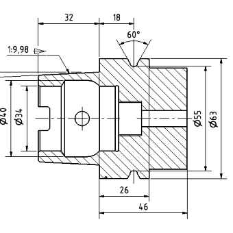
Technical drawings are key documents in manufacturing, so they must clearly specify nominal dimensions and allowable deviations. Proper marking of tolerances allows for unambiguous reading of the specifications and avoids interpretation errors that could lead to assembly problems or additional machining costs.
Basic rules for determining tolerances on a technical drawing
- Use of appropriate markings in accordance with ISO and ASME standards
- Dimensions should be shown legibly, without unnecessary repetition.
- Geometric tolerance markings must be in accordance with ISO 1101 or ASME Y14.5.
- Dimensions and their tolerances must be placed in the appropriate locations on the drawing to not interfere with legibility.
- Specify geometric tolerances for key components
- Instead of using the classic ± tolerances for each dimension, it is useful to use geometric tolerances that better represent the component’s functionality.
- For example, the tolerance of flatness is important for tangential surfaces, and parallelism is crucial for slideways and plain bearings.
- Dimensions important for assembly should be designated as control dimensions (e.g., K, C in the technical documentation).
- Avoid over-tightening tolerances if it is not necessary
- A common design mistake is adopting very tight tolerances, which increase manufacturing costs.
- Use tolerance classes matched to the function of the part – for precision parts (such as bearings), it is worth using IT6 classes, and for structural parts, IT10-IT12 will suffice.
- According to ISO 2768, general tolerances can be used for parts that do not require high manufacturing accuracy.
- Ensure compatibility with measurement methods
- Tolerances should be selected in such a way that they can be controlled with available measuring tools.
- For example, if the tolerance is less than 0.01 mm, standard calipers may not provide sufficient accuracy, and a coordinate measuring machine (CMM) will be needed.
Dimensional inspection methods
|
Measurement method |
Description |
Scope of application |
|---|---|---|
|
Caliper |
Simple tool for measuring length, diameter, and depth, accuracy of 0.02 mm. |
General production, fast dimensional control. |
|
Micrometer |
A tool for precise measurement of diameters to the nearest 0.001 mm. |
Control of critical dimensions. |
|
Dial gauge (index gauge) |
Used for checking axial runout and perpendicularity of surfaces. |
Inspection of shafts, gears, and bearings. |
|
Coordinate measuring machine (CMM) |
An advanced 3D scanning system that accurately measures geometric and positional tolerances. |
Aerospace, precision mechanics, automotive. |
|
Measuring projector (profilometer) |
Optical method for measuring surface contours and profiles. |
Inspection of workpieces with complex shapes. |
|
3D laser scanner |
A non-contact scanning system is used to analyze the entire surface of an object. |
Deviation analysis in CAD technology, 3D printing. |
Practical aspects of using tolerances include precisely determining allowable deviations on technical drawings and effective methods for controlling them. Using the right standards and measurement tools can minimize the risk of production errors, ensure correct assembly, and optimize production costs. Today’s technologies, such as statistical process analysis and advanced measurement systems, enable even more accurate control of dimensions and tolerances, which is crucial for modern industry.
Dimensional tolerances – a summary
Proper selection of dimensional tolerances is crucial to ensuring proper assembly of components in various industries. Inappropriate tolerances can lead to fit problems that increase costs, material losses, and compromised product quality. Therefore, engineers must carefully analyze tolerance requirements, taking into account both functional and economic aspects, to ensure the reliability and efficiency of assembly processes.
